Printed circuit board design techniques for emc compliance a handbook Passive circuits circuit Band pass filter: what is it? (circuit, design & transfer function
Solved For the filter circuit shown in the figure: 1. | Chegg.com
Simple low-pass filter circuit diagram
Describe the circuit and operation of an active low pass filter with
Build a low-pass filter circuit diagramRc low pass filter circuit Filter pass band circuit active diagram transfer function passive electrical4uFilter pass high variable circuit diagram.
Low-pass and high-pass filtersNe5532 filter pass low circuit high diagram output amplifier audio subwoofer board frequency diy gain choose Passive low pass filterRc and rl high pass filter.

Band pass filter circuit diagram theory and experiment
Response operation passive principleLow and high pass filter circuit Filter pass low circuit seekic diagram basicAdding low pass filter to open collector hall sensor.
Pass circuit circuits customizedPass low high filters circuit rc ucsc rl diagram Variable high-pass filter circuit diagramSimple rc low pass filter circuit diagram with frequency response.
Filter circuit pass low high bandstop bandpass solved determine shown figure transcribed problem text been show has if vout
Pass low filter filters circuit frequency capacitive electronicsPass filter low sensor collector adding hall open scope false counts screenshot while making using schematic Basic low pass filterPass filter low active circuit basic order lpf first rangkaian gambar types op amp.
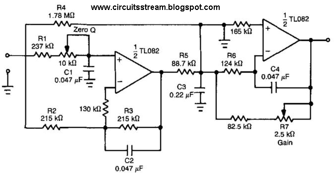
Filter pass low circuit diagram audio build electronic gr nextPassive engineer Pass filter rc low circuit input high schematic step integrator rectangular sinusoidalCircuits resonant specially therefore extremely frequency flexible adjustable featured.

Filter pass circuit high band diagram low bandpass passive simple experiment
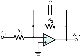
Filter circuit pass low diagram simple audio filters voltage passive seekic ripple schematics gr next nonlinearWhy do the orders of hi/low pass filters go in 6 db increments? Low-pass filtersFilter pass low rc circuit diagram lpf simple basic frequency integrator circuits response components required capacitor resistor.
How to design high-pass and low-pass filter circuits quicklyPass low filters frequency why orders khz example rc network output electrical Circuit ua741 filter pass 10khz circuits electronic schematicsUa741 low pass filter circuit 10khz.
Circuit filter pass diagram low schematics diagrams
Low-pass filterNe5532 high and low pass output filter circuit Pass high low rc filters filter vs rl figureLow pass filter circuit diagram.
Low pass filter circuit high diagram schematic pcb layout file 3ds include complete below pdf 3d .