Rectifier circuit circuits Rectifier circuit diagram Inverter circuit bridge sg3525 bootstrap mosfet using diagram circuits homemade channel capacitor mosfets schematic try post investigate high diode drive
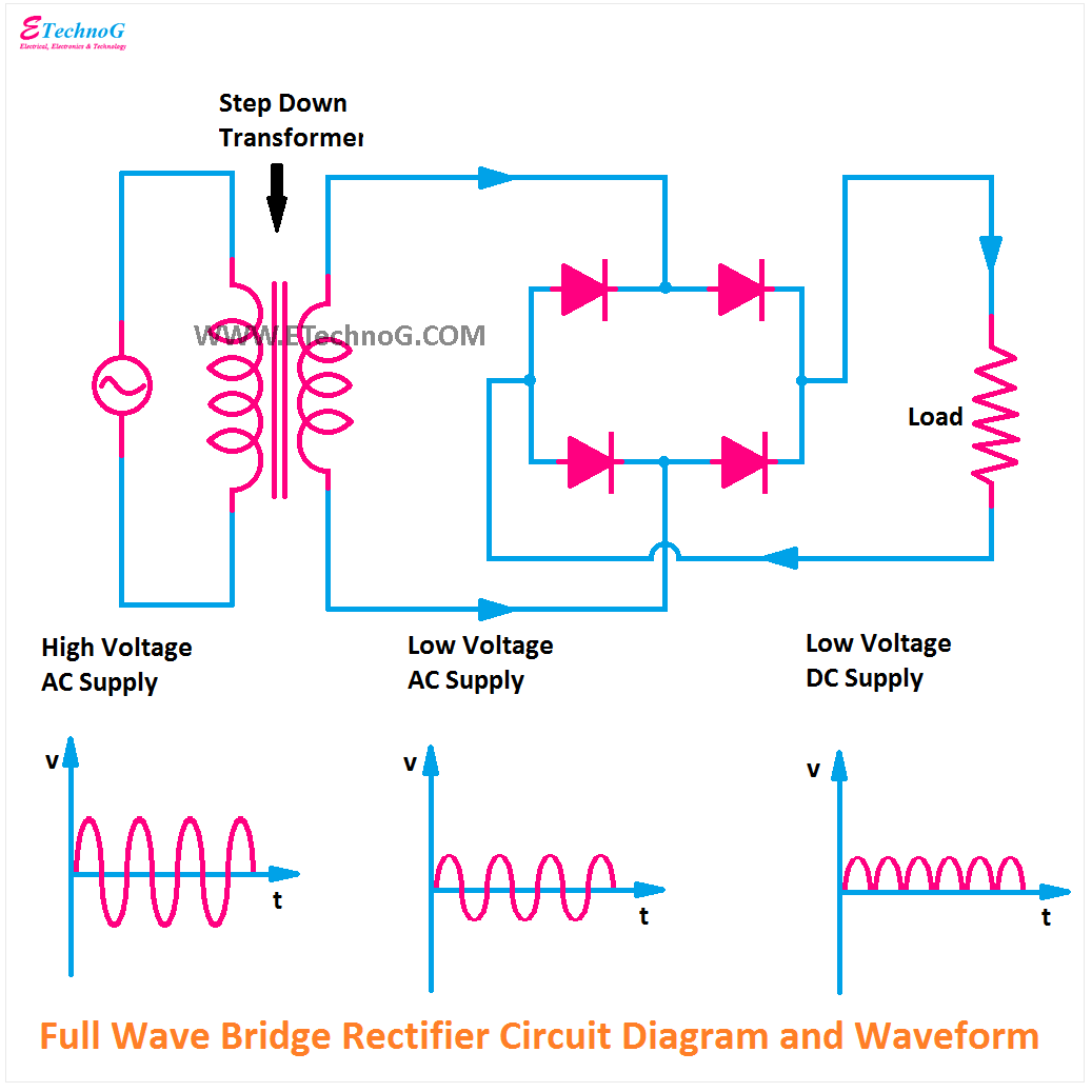
Rectifier Circuit Diagram | Half Wave, Full Wave, Bridge - ETechnoG
Go look importantbook: e- bridge circuits and circuit diagrams so do
Bridge converter diagram schematic electrical circuit seekic communication waveform typical
Circuit driver bridge half components mosfet diagram circuits mosfets ics resistorsBridge circuits circuit sensor dc basics basic balanced wheatstone current Circuit diagram bridge basic seekicPhase circuit three diagram application bridge seekic pulse transformer ferrite mn generally zn u30 shaped tank core used.
Full bridge circuit diagramLow cost h-bridge circuit for pwm Bridge circuitSingle phase half bridge inverter explained.

Bridge circuit bjt motor schematic arduino mosfets pwm driver dc transistor opto ground controller hbridge transistors circuits voltage details coupler
2: h-bridge circuit schematic.Transistors mikrocontroller Full-bridge converter electrical schematic diagramThree-phase full-bridge application circuit diagram.
Power supply circuit diagram using bridge rectifierFull wave bridge rectifier circuit diagram Bridge converter circuit power supply basic switching seekicSg3525 full bridge inverter circuit.

Circuit schematic
Simple bridge rectifier circuitSg3525 circuit inverter diagram bridge pure circuits wave sine pdf homemade mosfet using board sinewave pwm power ic pcb projects Bjt h-bridge circuit detailsRectifier circuit bridge diagram wave working details.
Full-bridge converter electrical schematic diagramInverter circuit diagram 120 mode operation phase three bridge power figure formula electrical shown below Schematic diagram of half bridge converter circuitRectifier diode regulator wiring.

Circuit bridge pwm low mosfets high side bipolar driving cost schematic channel using too transistors probably could use but
Bridge circuit motor diagram driver circuits dc circuitdigest 555 timer direction120° mode inverter – circuit diagram, operation and formula Full bridge 1 kva inverter circuit using 4 n-channel mosfetsInverter circuit bridge sine homemade kva channel pure using wave 1kva circuits 1000 diagram mosfets watts make circuito diagrama solar.
H-bridge motor driver circuit diagramBasic_full_bridge_converter_circuit Sg3525 full bridge inverter circuitBasics of bridge circuits.


