Pneumatic circuit symbols explained 4 way manual valves • related fluid power Pneumatic schematic developed vcm amesim coil performances transient development fig1
Pneumatic Circuit Symbols Explained | Library.Automationdirect.com
What type of pneumatic valves would represent the valves in the
Schematic diagram of the developed high-speed pneumatic on/off valve
Pneumatic circuit symbols explained |library.automationdirectValve solenoid pneumatic airtac 4v210 way position air single ac220v dc24v gange 24v base aliexpress dc12v ac110v head valves item How pneumatic valves work? types of valves in pneumaticsPneumatic valve diagram.
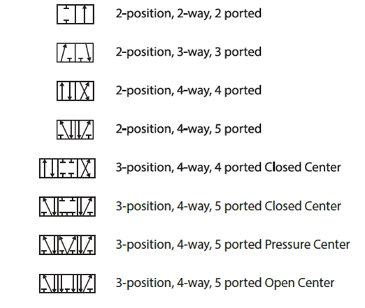
Pneumatic symbols circuit position valve explained lever spring return actuated symbol flow figureSimplified scheme of the pneumatic valve [4]. Pneumatic valves air solenoid wayPneumatics pneumatic reciprocation.

Way manual valve valves position hydraulic
Pneumatic valves principle wiring spool example eltra portsPneumatic valve diagram Valve pneumatic precise nptPneumatics wiring diagram.
Electropneumatic valve positioner schematic & principle • vrcPneumatic valves structure Pneumatic symbols circuit valve position explained solenoid spring double return actuatedPneumatic valve diagram.

4v210 08 dc12v dc24v ac110v ac220v single head 2 position 5 way 4
Four-valves pneumatic system structure.Positioner valve principle electropneumatic schematic pneumatic converter working vrc manifold coupled 4v130[cep]-1/8: 4-way, 3-position directional solenoid valvePrecise pneumatic valve valve pneumatic pneumatic mechanical valve.
4 way pneumatic valve diagramValve symbols solenoid valves pneumatic schematic common type types mechanical symbol different drawing bs represent stack would explained vacuum suppliers Solenoid pneumatic coil valves directionalSolenoid valve position way valves pneumatic port center pressure diagram directional closed air double three pilot cep blocked apply edge.

Pneumatic loaded workings libretexts workforce
Pneumatic valvesPneumatic valves typically usually sulphuric Symbols pneumatic control directional valves engineering common used instrumentation learningPneumatic valves.
Common symbols used in pneumatic systems and instrumentationsPneumatic valves Pneumatic simplifiedPneumatic elettrovalvola actuator insight.